With my desire to constantly make thing better I decided it was time to improve upon my first version of the DIY power roof vent.
The first version worked very well and performed everything I designed it for, with both fans running on high it ventilated the interior to reduce humidity and condensation (65 cfm full interior air exchange approx 5 minutes), extremely low current draw (0.2 Amps), and be almost silent so it could be left on all night (<20 dB-A).
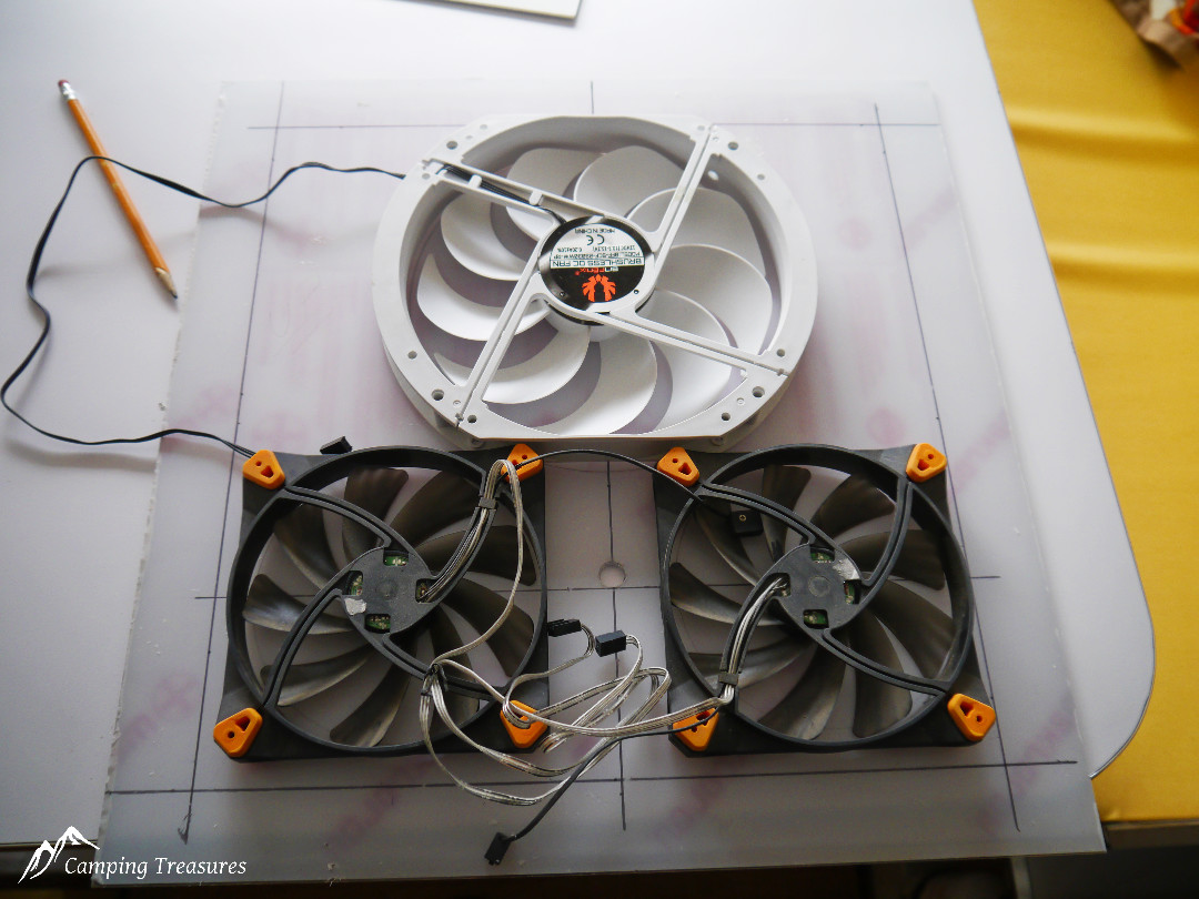
So what can be done to improve it? adding a third 230mm (9″) computer fan that really gets the air flowing when needed. For this modification I relocated the two 140mm fans and wired them together so they could still be used for regular ventilation and silent operation at night. I added a Bitfenix Spectre 230mm Fan that adds 98 CFM (total airflow increases to over 160 CFM, this fan also draws only 0.2 Amp at <20 dB-A. Theoretically this should change the air inside the Boler once every 2 minutes.
You are probably asking yourself “why go to all this work when you can just buy a Fantastic fan”. well there are actually several reasons:
- Noise, or really lack of noise, I want to be able to leave the fan on at night and not be able to hear it
- Low current draw, we boondock a lot and don’t want to worry about draining our battery
- The challenge, why buy something when you can build it
| DIY Fan | Fantastic Fan | |||
| Current Draw – Low | 0.2 Amp | √ | 1.9 Amp | |
| Current Draw – Medium | 0.2 Amp | √ | 2.3 Amp | |
| Current Draw – High | 0.4 Amp | √ | 3.0 Amp | |
| Air Flow – Low | 65 CFM | 478 CFM | √* | |
| Air Flow – Medium | 98 CFM | 653 CFM | √* | |
| Air Flow – High | 160 CFM | 920 CFM | √* | |
| Decibels | 20 dB-A | √ | 40 dB-A |
* Although the Fantastic fan will provide considerably more airflow I do not think it is needed in such a small trailer
Design considerations:
- Fit all 3 fans into that standard 14″x14″ vent opening
- Keep interior shroud as close to the ceiling as possible
- Fan openings in baffle that prevent back-flow
- insect screen with access to area above fans for cleaning
- Allow as much light into the trailer as possible
Parts:
- 2 – 140mm computer case cooling fans* $17.00 ea
- 1 – 230mm computer case cooling fan* $17.00
- 4′ – 4 wire trailer plug wiring harness $.9.00
- 12 -8-32×1½” flat head machine screws w/nuts (to attach fans to mounting plate)
- 4 – 8-32×1¾” machine screws (to attach fan assembly through roof vent)
- 4 – 8-32 thumb screws
- ¼” acrylic, polycarbonate or plywood (approx 18″x18″ to cut to size)
- ½”x1½” acrylic, polycarbonate or plywood strips (approx 6′ length)
- Wire & switches (as needed)
- Heat shrink tube
*I bought my fans through Memory Express, review the fan specification for noise level and current draw.
All the fans I used had noise levels of under 20 dB and max current draw of 0.2A.
Tools:
- Jig saw
- Drill with bits
- Screwdriver
- Tape measure
- Straight edge
- Pencil or marker
- Soldering gun w/electrical resin core solder
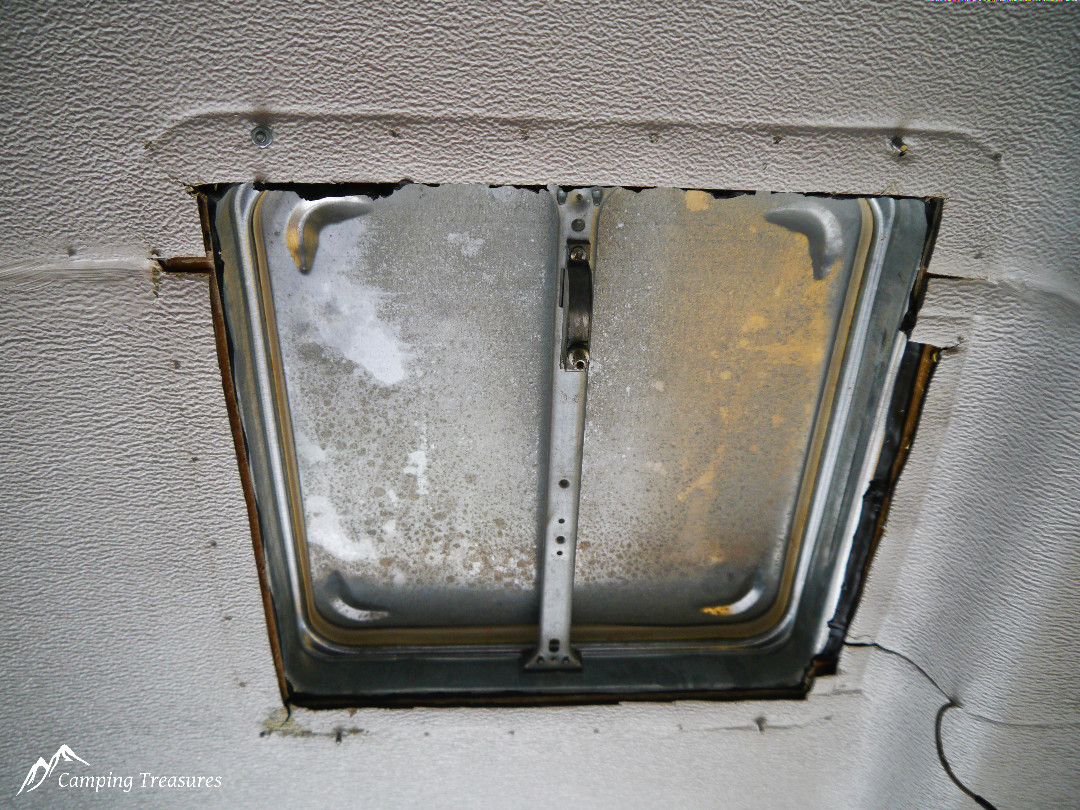
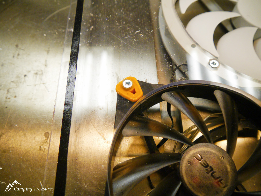
First I needed to remove interior bezel and trim (and fans) of the first version. I am using the metal roof vent which is fastened directly to the roof using butyl tape to seal and 8-32×1/2″ machine screws to secure it. My review of this roof vent is mixed, I love the vent, with the outside being metal it is almost indestructible, the negative is the inside bezel and trim are cheaper plastic that had started to crack. This fan conversion completely replaces all the original trim and plastic so all the negative aspects of the roof vent are gone
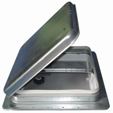
The original version ready to be removed
With the interior trim removed a cardboard template is made to determine the best placement of the fans. You also need to make sure the fans fit under the mechanism for opening the roof vent. I decided to mount the fans on 3/16″ thick piece of clear polycarbonate (Lexan) to let in as much light in as possible. (had some left over from making the windows) but you could easily use ¼” thick plywood. The measurements from the cardboard template are transferred onto the protective covering of the 3/16″ thick polycarbonate (or the ¼” thick plywood).
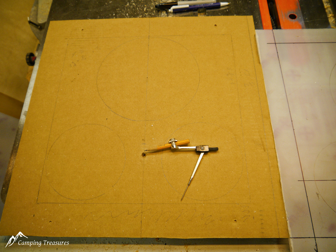
Cardboard template marking perimeter and fan locations

Template transferred to the polycarbonate protective film
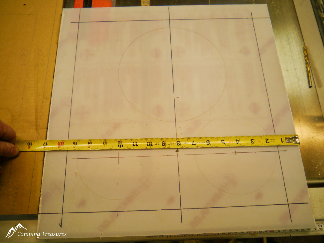
showing measurements to centres of small fans
Note: ther fans are slightly offset from centre
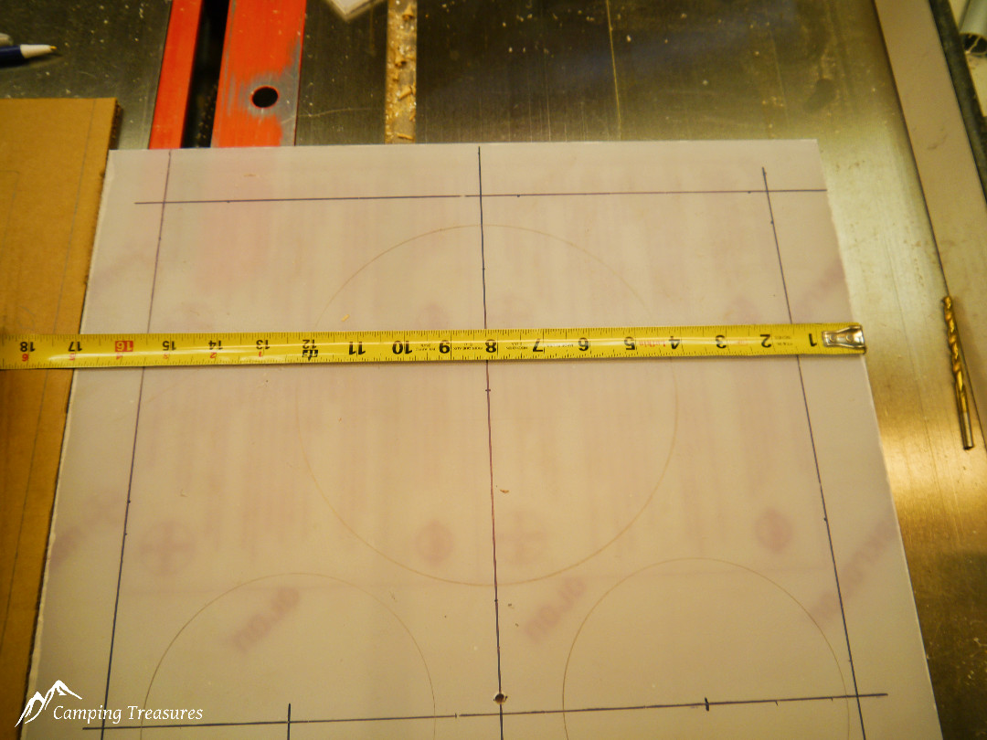
Location of large fan
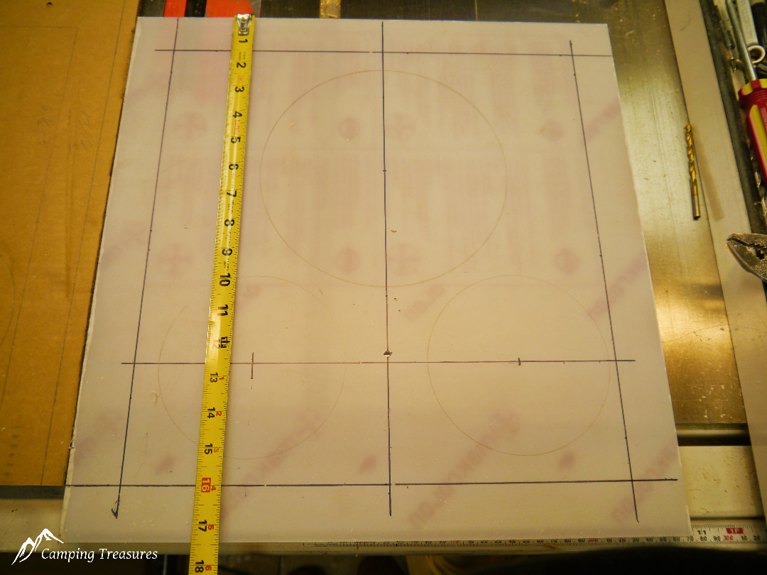
Small fan measurement
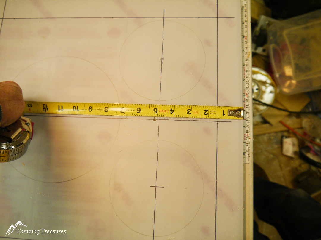
Small fan measurement
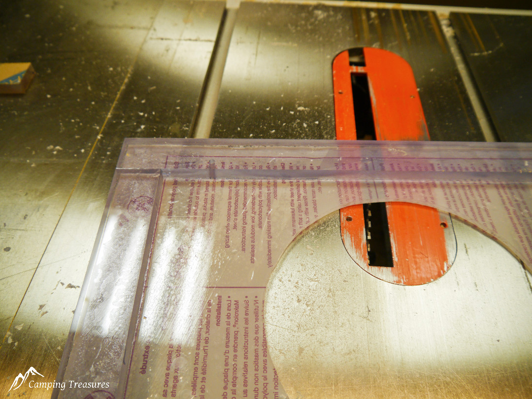
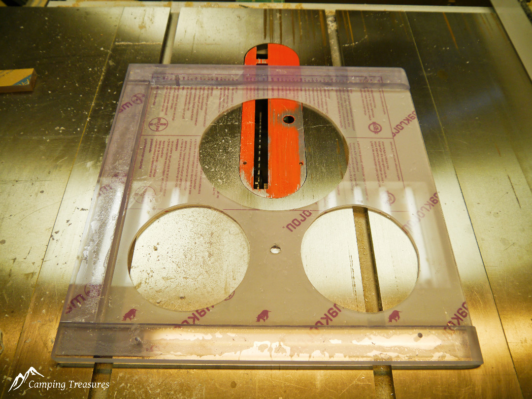
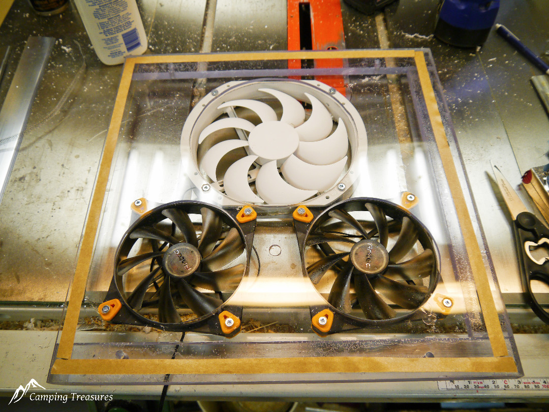
Holes are cut through the polycarbonate (or plywood) with a fine tooth metal blade in a jig saw. The fans are then mounted using #8-32×1½” flat head machine screws using countersink holes to keep the surface smooth.
Checking fan locations
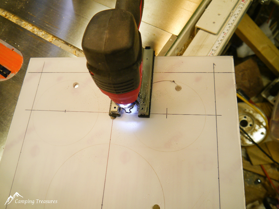
Cutting holes with jig saw and fine tooth metal blade
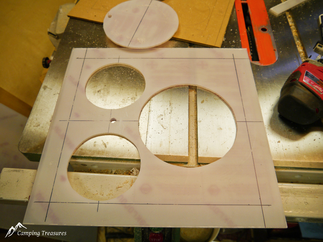
Holes cut
I used ½” thick strips by 1 ½” wide of polycarbonate around the 3 sides to space it down from the ceiling slightly (none was used on the side facing the kitchen wall to allow room for the curved area of the trolley top). The pieces are “glued” together with Methylene Chloride solvent which essentially melts the polycarbonate and welds itself together. If using plywood to mount the fans on then use ½” plywood strips and wood glue to attach the strips to the edge of the mounting board.
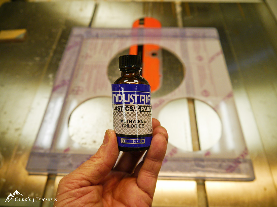
Methylene Chloride is used to weld the edge strips to the mounting plate
Edge strips solvent welded into place
Completed fan plate
A thin strip of butyl tape is placed around the perimeter to hold the screen in place. Aluminum screen is cut to fit the surface and held in place with 1½” wide aluminum trim.
Fans mounted and butyl tape applied around edge
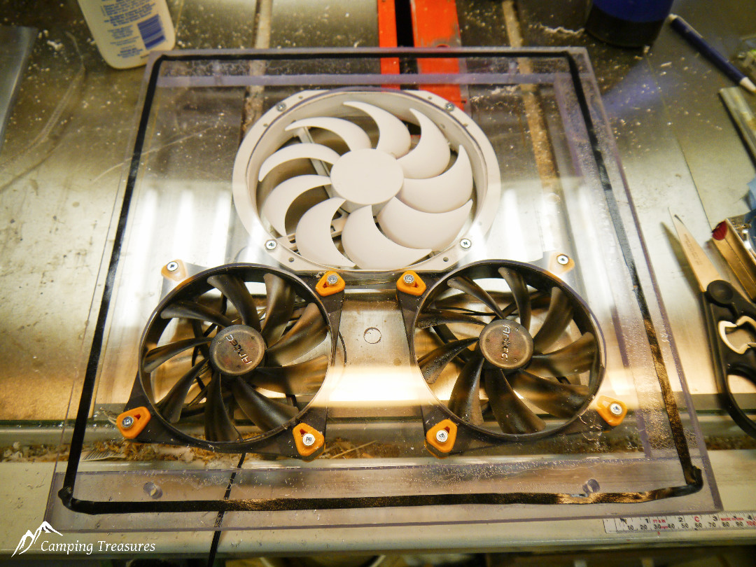
Release paper on butyl tape removed
The aluminum screen will be pressed into the butyl tape to hold it in place
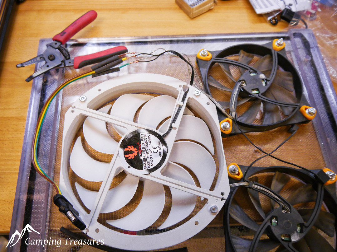
I control the fans through two switches, one switch controls the two smaller fans together and the second switch controls the large fan, this allows for “Low” using just the 2 small fans, “Medium” using just the large fan, and “High” when all 3 fans are running. Most computer fans use 3 wires, 12VDC+, 12VDC – and a signal wire. To figure out which wire simply connect the centre wire to a 9VDC to 12VDC battery (for testing you can use a small 9 volt battery), then touch one of the outer wires to the battery negative terminal the centre wire is 12VDC+. When connected correctly the fan will run. I used a standard flat 4 wire trailer connector so the fan assembly can be removed easily, the flat wires also slip easily behind the ensolite wall covering so the wires are concealed. Just carefully peal the ensolite away from the fibreglass at a seam, position the wire behind the ensolite, apply some contact cement to the fibreglass and back of the ensolite and press firmly together. A little Dap DynoFlex 230 caulking along the seam completes the electrical.
The wires spliced and ready for solder, Note the heat shrink is placed over the wire before joining them.
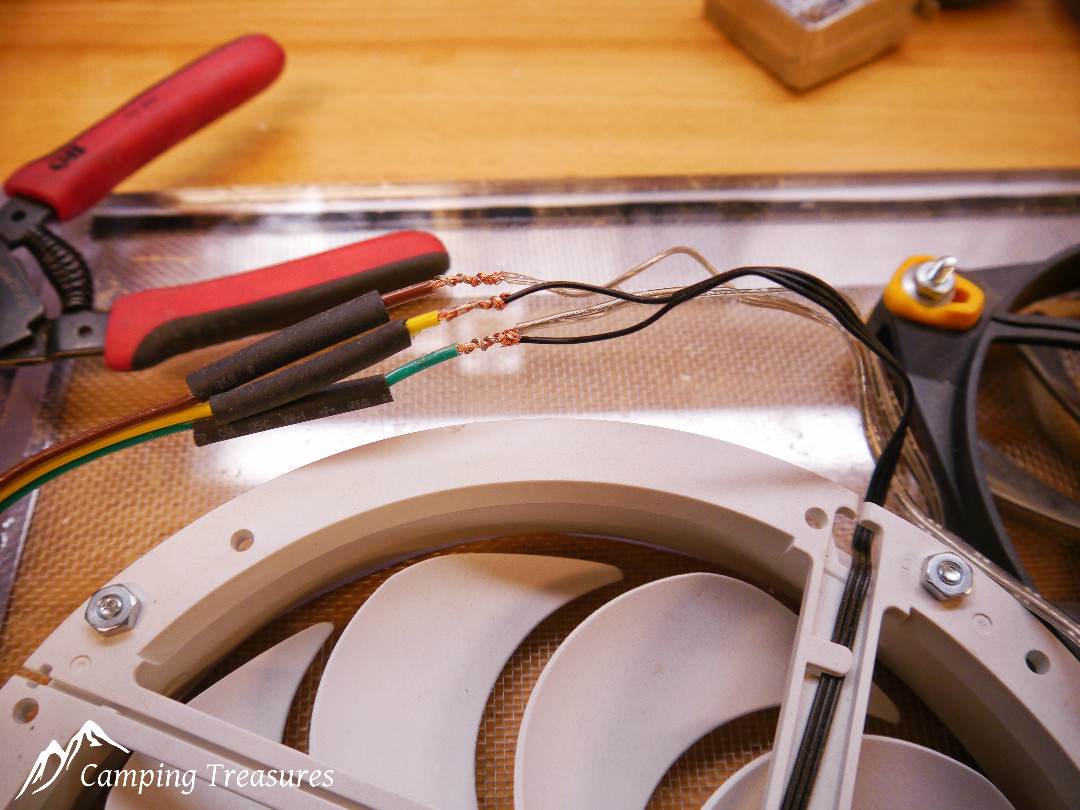
I use an inline splice which keeps the wires in line and results in a very neat and strong splice
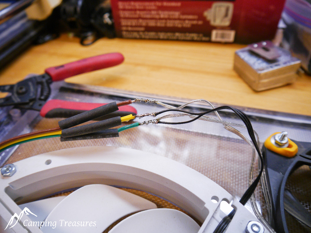
Here all the splices have been soldered
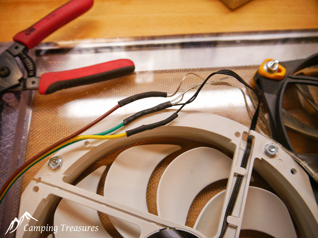
And finally the heat shrink tube is installed
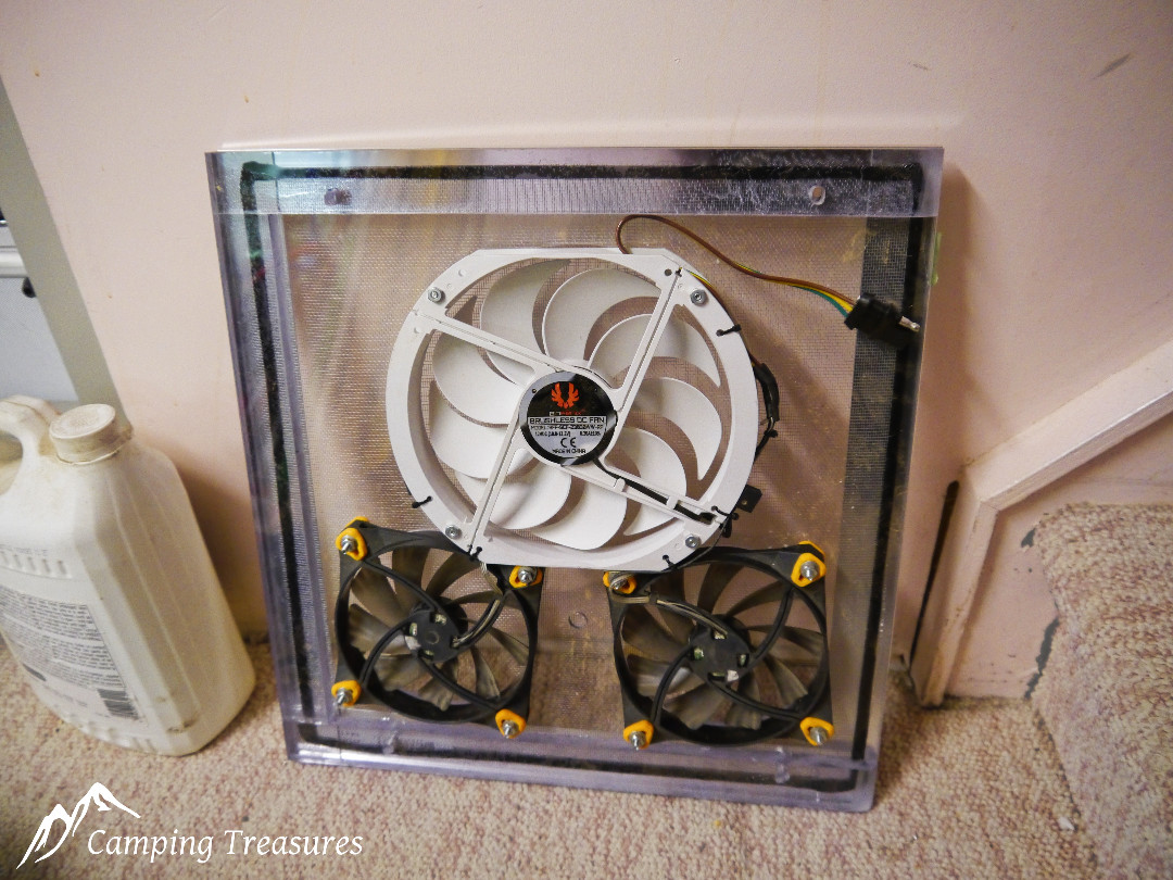
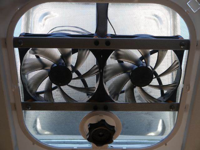
The finished fan with wires tucked away neatly, ready to install
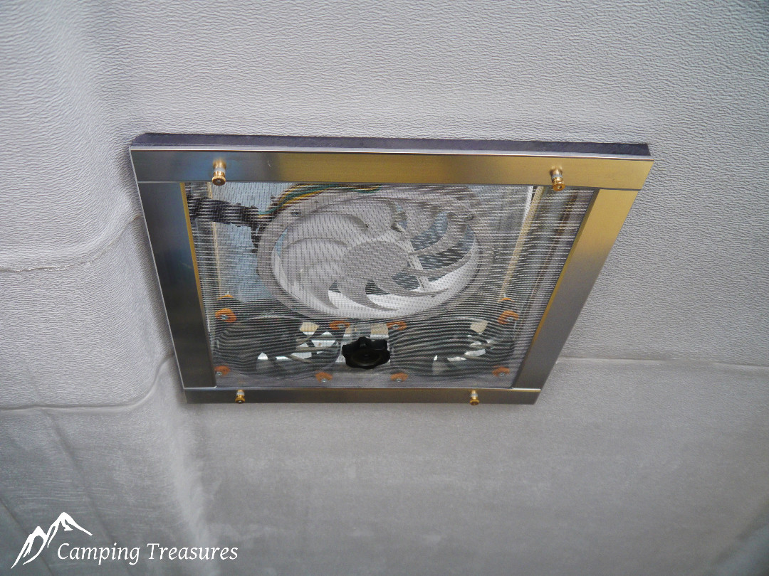
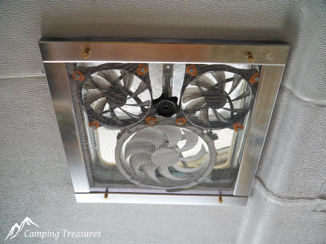
To mount the fan assembly I removed 4 of the machine screws used to attach the corners of the vent to the roof and replaced them with longer 8-32 machine screws. The entire assembly is slipped over these screws then small brass thumb screws are used to hold the fan assembly in place, this makes it easy to remove for cleaning.
Jean
What a great Idea !
Tara
That looks great. You by chance would not make one to sell would you?
Ian
I wish I had the time, but no I don’t sell complete units, sorry
Cheryl Morrice
Can you tell me how many millimetres in height the fans are? I could not find the appropriate fans when going through all the selections to be made. I want to build your fan, but I do not have enough experience with electronics jargon. Could you possibly tell which exact fans to purchase from Memory Express?
Ian
Hi Cheryl. The 230mm fan I mention are difficult to find now, but if those are not available you could use four 140mm fans or just less fans.
Memory Express lists the 140mm fans https://www.memoryexpress.com/Category/Cooling?FilterID=bf5a1d49-7acf-6d45-c2de-d6f4ccceb3a4
Amazon.ca listing for 140mm fans, https://www.amazon.ca/140mm-Case-Fan/s?k=140mm+Case+Fan
while considering price you want the lowest dB (noise level), highest CFM, and lowest currnt draw (amps)